Using Your Own Data
This section explains how to record IR/RGB videos of your own PV plant with your own camera and drone hardware in a way that is compatible with PV Hawk.
Hardware setup
For the development and testing of PV Hawk we used a DJI Matrice 210 drone with the DJI Zenmuse XT2 IR/RGB camera (variant with 13 mm focal length). However, PV Hawk should work with any other drone and camera as long as some basic requirements are fullfilled.
Drone requirements
Our drone records its GPS longitude and latitude in WGS84 coordinates at a rate of 1 Hz. PV Hawk performs internally a piecewise linear interpolation of the GPS trajectory to match the GPS measurement rate to the higher video frame rate. A higher measurement rate than 1 Hz is still desirable. Further, we ignore the altitude measurement of our drone as it is based on the barometer alone and not accurate enough. PV Hawk can handle this missing altitude. However, results will be more accurate and stable when an accurate altitude measurement is provided. Thus, we recommend using Real-time kinematic (RTK) GPS, which provdies centermeter-accurate longitude, latitude and altitude measurements.
Camera requirements
While the Zenmuse XT2 provides both a thermal IR and a visual RGB stream, PV Hawk works also when only RGB or IR videos are available. Thus, a dual IR/visual camera is not required. Your thermal IR camera needs a resolution of >= 640 px * 512 px and a frame rate of >= 8 Hz. The temperature range has to match the expected temperatures, which should be between -20 °C and 200 °C. Note, that some cameras automatically change the gain depending on the temperatures measured. Make sure that the gain is kept constant during the entire measurement of a PV plant. The focal length should be choosen so that a sufficient number of PV modules can be captured at a time. The exemplary video frames below should give you an idea of how the optical characteristics of your camera should be choosen.
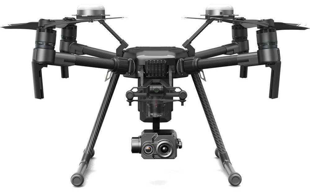
Fig. 1 DJI Matrice 210 with Zenmuse XT2 is one possible hardware setup for PV Hawk. Other drones and cameras can be used as they meet some minimum requirements. (Image source: www.brandonoptics.com)
Camera calibration
PV Hawk requires calibrated parameters of a pinhole camera model for the georeferencing of PV modules. To obtain these parameters a camera calibration needs to be performed. Calibration needs to be performed only once for a camera.
Calibration requires a target such as the one in Fig. 2. While the pattern is a standard checkerboard (see here), the target must be visible in the IR spectrum. Simply printing the target onto paper does not work. Instead, the target needs to be made of materials with different thermal emissivity for the black and white squares. We obtained good results using black foil squares applied to a white polymer panel. Also make sure that images are as blur-free as possible with good contrast between white and black squares.
We provide a Jupyter notebook for camera calibration in calibration/01_calibrate.iypnb. Information on the usage is provided in the notebook. To run the calibration notebook, first start an interactive Docker session as described in Step 4: Run the Docker container. Then start jupyter lab in in the interactive Docker session with the command
jupyter lab --allow-root --ip=0.0.0.0 --port=8888
Note, that the port number must match the port forwarded when starting the Docker container. Open the displayed URL in the web browser on your machine. In jupyter lab navigate to calibration and open the 01_calibrate.ipynb notebook. Make necessary changes, and then run the notebook.
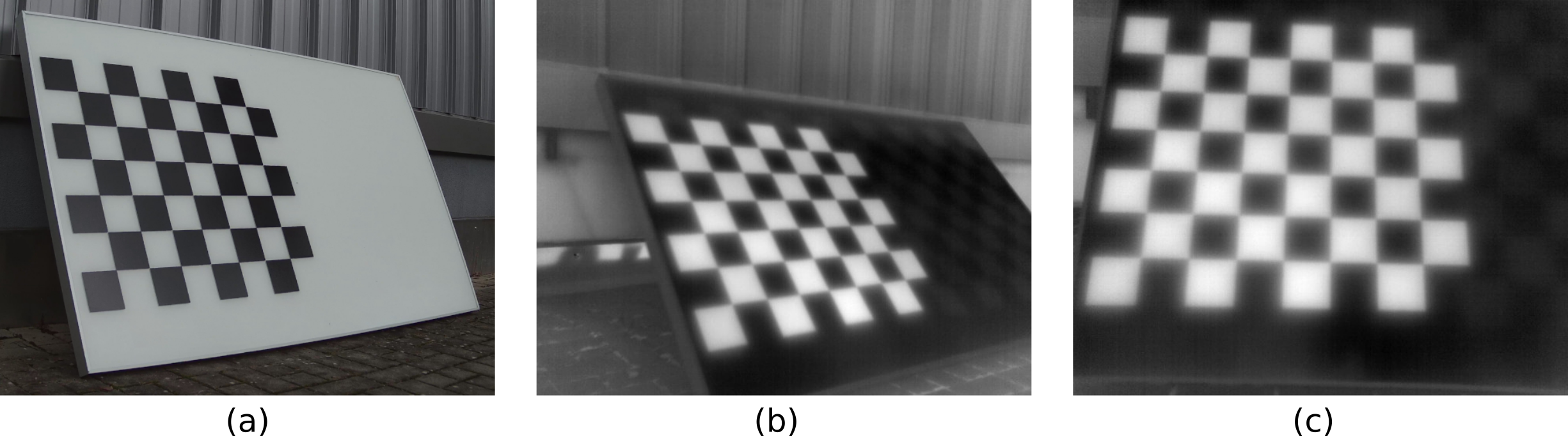
Fig. 2 Exemplary target for calibrating a thermal IR camera. (a) shows a visual RGB image and (b) and (c) are thermal IR images.
Video recording
While PV Hawk is flexible with respect to the way IR/RGB videos are recorded, several rules must still be followed to ensure optimal results. In general, you should scan PV plant rows one or two at a time as indicated in figure Fig. 3 and Fig. 4. Resulting video frames are shown in Fig. 5. Scanning two rows at a time increases throughput but also reduces the resolution of extracted PV module images. While the rows can be scanned in an arbitrary order, we recommend sequential scanning to simplify the subsequent manual configuration. The drone flight can be automated or carried out manually.
We recommend to orient the camera facing vertically downwards (nadir) at all times. This improves robustness of the processing pipeline as we can set a vertical orentiation prior in OpenSfM when reconstructing the camera trajectory. However, at the expense of lower robustness you can also choose a non-nadiral camera angle. This is useful, for instance, to prevent sun reflections on the PV modules.
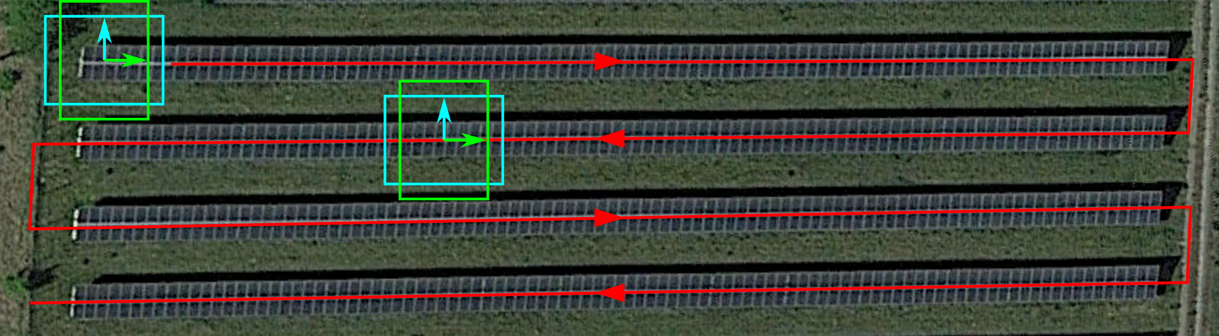
Fig. 3 Scanning of a single PV plant row at a time. Boxes indicate the camera viewport and arrows the up-direction of the video frame. The camera is oriented so that the plant row lies either horizontal (cyan box) or vertcial (green box) in the video frame. Important is not to rotate the drone/camera at the end of the row. Instead, keep the heading constant and fly backwards as indicated by the second set of boxes.
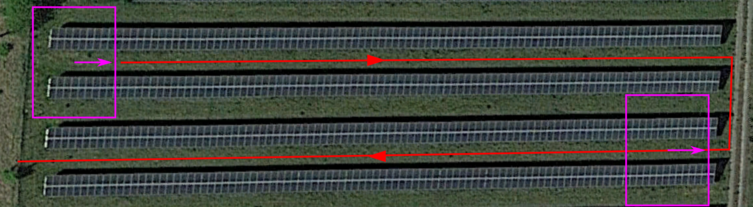
Fig. 4 Simultaneous scanning of two PV plant rows by increasing the flight altitude. Again, the heading must be kept constant when changing rows.
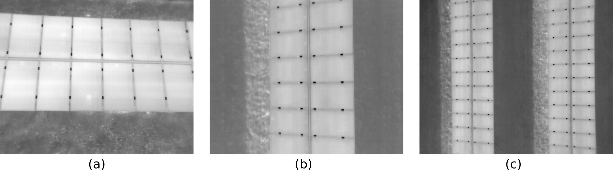
Fig. 5 Exemplary IR video frames for (a) horizontal scanning of a single row (cyan box above), (b) vertical scanning of a single row (green box above), and (c) scanning of two rows at a time (magenta box above).
In the following, we list all the rules you should follow when recording IR/RGB videos for PV Hawk. We differentate between hard rules and soft rules. If you do not follow the hard rules PV failure is guaranteed. Not following one of the soft rules may not result in immediate failure, but can decrease robustness of the processing piepline.
- Hard rules:
Never tilt the camera, instead keep it rigidly oriented w.r.t. the drone.
Never change the heading of the drone absruptly, e.g. never yaw the drone at the end of a row.
Move the drone a sufficient distance in at least two orthogonal directions, e.g. north/south and east/west. Flying only along a line is insufficient.
- Soft rules:
Point the camera down vertically (nadiral)
Keep the viewing angle vertical enough so that no rows become visible in the background (see Fig. 6 a)
Do not truncate the scanned row at the top/bottom of the video frame (see Fig. 6 b) except when you change to the next row
No neighbouring rows should intrude the video frame at the top or bottom (see Fig. 6 c) except when you change to the next row
Avoid abrupt movements (fly with constant velocity, slow enough to prevent motion blur)
Avoid scanning the same plant row multiple times
Move the camera monotonically along each row, i.e. do not move backward
Maintain a constant altitude (if your GPS provides no accurate altitude measurement) or better maintain a constant height over the modules (only if your GPS provides an accurate altitude measurement)
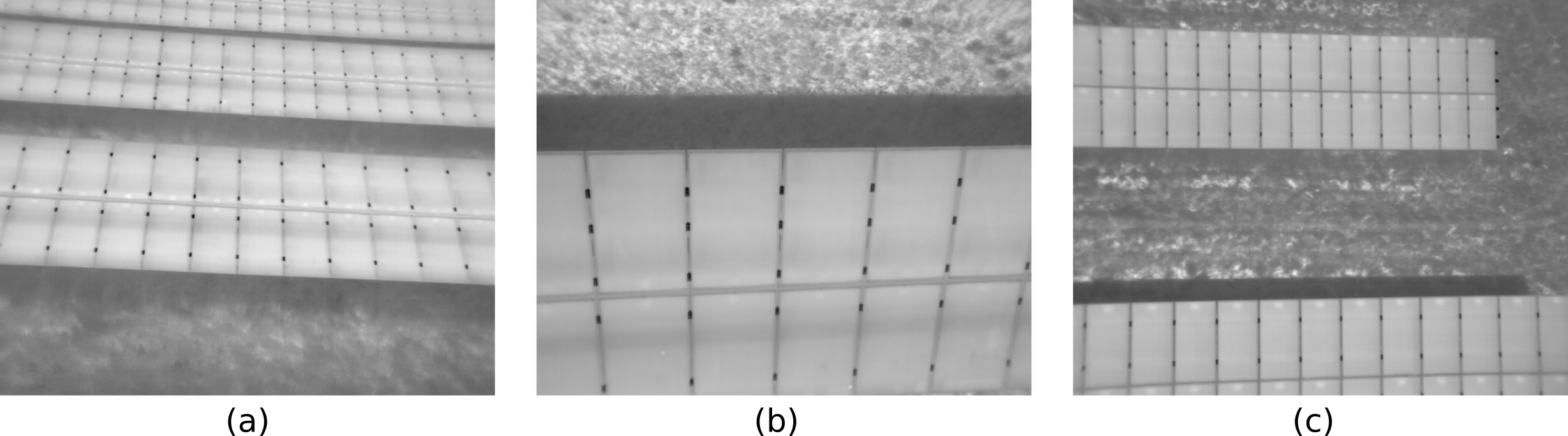
Fig. 6 Examples of invalid video frames: (a) Background rows visible, (b) scanned row truncated, and (c) neighbour row intruding.
Below are some images and videos of valid recordings.
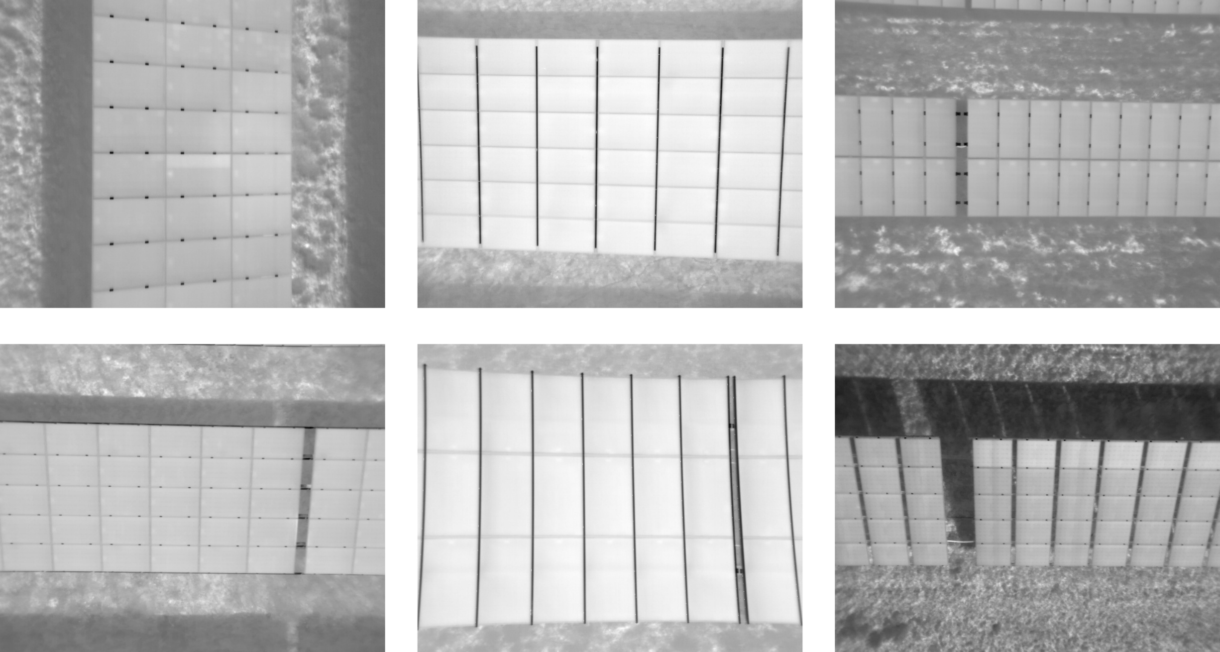
Fig. 7 Examples of valid IR video frames.
As mentioned earlier, you can choose a non-nadiral camera angle to prevent sun reflections on the PV modules. However, you may not always be able to completely prevent sun reflections. For this case, we provide a sun reflection filter in the PV Hawk Viewer.
Weather conditions are another important aspect to consider. For optimal results, the sky should be cloudless and solar irradiance should be above 700 Watt/m². Lower irradiance typically results in IR images with low contrast, which is challenging for the automated processing. Furthermore, module anomalies are less visible at low irradiance.
Note
We limit the description above to row-based PV plants as we have not yet extensively tested PV Hawk on non-row-based PV plants (see also Current Limitations). While the rules above also apply to non-row-based PV plants, you may have to consider additional aspects. For example, scanning a large array of PV modules may require multiple overlapping “sweeps”.
Dataset creation from videos
After recording, you need to convert the IR/RGB videos of your PV plants into a format compatible with by PV Hawk. The directory tree below shows the various files required by PV Hawk. The directory must be named splitted and must be located in the work_dir specified in the config file.
/workdir
  |-- splitted
  |    |-- timestamps.csv
  |    |-- gps
  |    |     |-- gps.json
  |    |-- radiometric
  |    |     |-- frame_000000.tiff
  |    |     |-- frame_000001.tiff
  |    |     |-- ...
  |    |-- rgb
  |    |     |-- frame_000000.jpg
  |    |     |-- frame_000001.jpg
  |    |     |-- ...
As indicated, you have to provide each video frame as a single image. Image names must follow the scheme frame_xxxxxx.tiff where xxxxxx is the frame index (incremented from zero) as 6-digit integer with leading zeros. IR frames must be placed in the radiometric subdirectory and RGB frames in the rgb subdirectory. IR video frames must be single-channel TIFF images of unsigned 16-bit integer values. RGB frames must be 8-bit JPG images with three channels (for red, green, and blue). It is fine to provide only RGB or IR, or both. PV Hawk only runs either on RGB or IR, but never uses both RGB and IR simulatenously. Whether RGB or IR is used can be configured with the ir_or_rgb parameter in the config (see also Config File Reference).
For faster processing, we recommend you scale down RGB images in case the native camera resolution is high. E.g., you may scale down 4K images to 1280 x 720 pixels or 1920 x 1080 pixels. In contrast, for IR images, we recommend to use the native spatial resolution of your camera, i.e. do not perform any resizing. Furthermore, do not perform any rescaling of the values but simply provide the raw values output by your camera. PV Hawk will internally normalize the value range. Ensure that your IR camera outputs linearized temperature values, i.e. the raw image values must be mappable to temperatures by means of a linear transformation (multiplication by a gain factor and subtraction of an offset). While this is the default for IR cameras outputting TIFF images, it does not apply to some proprietory formats, such as the SEQ or radiometric JPEG format.
Furthermore, you must provide the GPS position of the drone at each video frame in a JSON file named gps.json in the gps subdirectory. The file must contain a list of lists, where each inner list is a triplet of [longitude, latitude, altitude] in WGS84 coordinates as shown below.
[
  [11.180329444444446, 48.613639722222224, 0.0],
  [11.180571349206538, 48.61362777777799, 0.0],
  ...,
  [11.179669479166668, 48.61309805555565, 0.0]
]
The GPS altitude may be zero if an accurate estimate is not available (see Drone requirements). For each video frame there must be one position. If your GPS measurement rate is lower than the video frame rate, you can replicate the same position for multiple frames. You should then use the pipeline task interpolate_gps to perform a piecewise linear interpolation and obtain a more accurate position estimate for each frame.
Finally, you should provide a timestamps.csv file, which contains the timestamp of each video frame in the exact same format shown below. The file is not immediately needed in PV Hawk. However, the PV Hawk Viewer uses it to estimate the flight duration and other quantitites.
2021-09-09T10:28:47.500000
2021-09-09T10:28:47.530000
...
2021-09-09T11:57:48.950000
Note
If you use a DJI Zenmuse XT2 or compatible camera, you can configure the camera to output IR videos as multipage TIFF stacks and RGB videos as mov files. Place the TIFF stacks and mov files in a videos subfolder in your work_dir and run the pipeline task split_sequences. This will automatically generate the splitted directory with all dataset files.